
Ceramic PCB Electroplating of Gold-Tin Alloy: Optimization of Production Processes
- Iva Leung
- Feb 16, 2024
- 4 min read

Gold-tin (Au-Sn) alloy boasts excellent thermal conductivity, mechanical properties, low melting point, good wettability after melting, and the advantage of soldering without the need for flux. It finds widespread application in the assembly and packaging of high-power heat dissipation components such as LEDs, laser diodes, RF power amplifiers, hermetic sealing, and semiconductor chip stacking.
The preparation methods of gold-tin alloy include solder paste reflow, solder preforms, evaporation, magnetron sputtering, alternate electroplating, and alloy electroplating. Considering factors such as cost, process complexity, and compatibility with tiny-sized circuits, alloy electroplating emerges as the optimal choice. This article primarily explores the main factors affecting the deposition of gold-tin alloy layers, introduces CNC dual-pulse power supplies and ultrasonic devices, designs measurement methods combined with electroplating fixtures and process parameters, and adjusts parameters such as electrolyte ion concentration, current density, and electroplating time based on measurement results to achieve target values of coating performance, thickness, and composition ratio.
I. Electroplating Equipment
Conventional electroplating typically employs DC power sources. It involves connecting a DC power source to a specific electrolyte solution containing a certain composition through relevant electrochemical principles to deposit the target metal or alloy on the surface of specific parts, forming a uniform, dense, and well-bonded pure metal or alloy coating, thereby enhancing the decorative, protective, or functional properties of the target parts. This process is a complex interplay of physics and chemistry.

The schematic diagram of the current loop during electroplating process, as shown in Figure 1, illustrates the flow of current from the positive pole of the power supply, through the metal wire into the anode of the gold-tin alloy electroplating, then into the gold-tin alloy electroplating solution, further to the solution to the part to be plated, and finally returning to the negative pole of the power supply, completing a circuit.
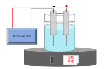
Here, dual-pulse CNC power supplies are introduced. In comparison to the direct current electroplating mode, during pulse electroplating of metal alloys, due to the conduction and interruption of current, the polarization effect generated in the cathode area of the electroplating solution is significantly improved.

II. Electroplating Fixtures
The biggest difference between electroplating alloys and electroplating single metals lies in that the current density not only affects the thickness of the coating but also directly affects the proportion of various components in the alloy. Therefore, to ensure the consistency of gold-tin alloy plating between and within boards, the design of electroplating fixtures is crucial. To reduce the impact of the fixture's own resistance on the current density, titanium-clad copper material is used to process the main frame. To ensure uniform current distribution within the board, multi-point energizing is generally adopted. For example, for a 2-inch square piece, at least 4 energizing points are required.

III. Electroplating Process Parameters
Typical process parameters for electroplating gold-tin alloy are listed in Table 1. The temperature is generally set at the recommended optimal value. pH can be adjusted using acid-base solutions recommended by the manufacturer, but it should be noted that pH is the measured value at the working temperature, not at room temperature.

IV. Adjustment of Electroplating Solution Concentration
To ensure the proportion of gold-tin alloy, the content of Au+ and Sn2+ in the plating solution needs to be analyzed after each shift, and the solution adjusted based on the analysis results.
Au+ and tin ions (including Sn2+ and Sn4+) can be analyzed using ICP (inductively coupled plasma) or AAS (atomic absorption spectrometry). The tin 2+ concentration is generally analyzed by titration. First, prepare the test solution (10 mL bath solution + 50 mL deionized water + 30 mL concentrated hydrochloric acid), then titrate with a potassium bromide solution (Br- 0.05 mol/L, equivalent concentration 0.1 N), observe the oxidation-reduction potential using an ORP meter (oxidation-reduction potential meter), and when the potential undergoes a sudden change, it indicates the end point of titration, then calculate the mass concentration of Sn2+ [ρ(Sn2+)]. The analyzed mass concentration of tin ions [ρ(total tin)] minus ρ(Sn2+) gives the mass concentration of tin ions [ρ(Sn4+)], thereby determining the oxidation rate of tin 2+ in the bath solution and estimating the solution's service life.


V. Batch Electroplating
When the plated area of the workpieces varies greatly, they should not be mixed in the same batch for plating, as the actual current density distribution on the surfaces of workpieces with different plated areas varies greatly, leading to significant differences in the composition of gold-tin alloy, which easily results in poor coating performance and low product qualification rate. For example, a graphic electroplated square with an area of 392 mm2 and a whole-board plated piece with an area of 2500 mm2 are plated in the same batch. The thickness and composition of the gold-tin alloy layer at different points are analyzed as shown in Figures 5 and 6. The mass fraction of Au in the alloy of the graphic electroplated product is (75 ± 1)%,
#PCB #Electroplating #GoldTinAlloy #ManufacturingProcesses #Engineering #CeramicSubstrate #Electronics #Tech #ProductionOptimization #EngineeringInsights #ProcessImprovement #IndustryInsights#AIN #AI2O3 #Infobright #InfoBrightTechnology #CeramicPCB #CeramicSubstrate #CeramicCircuitBoard #Manufacturer #semiconductor #Design #Lighting #LED #LED #COB #microwavecommunication #powermodules #Electronics #PCBDesign


Commentaires